by Raymond Yee | March 1, 2019 | 3D Repository, Accessories, Miscellaneous, Photography, Photography Accessories, Video, Video Accessories
Following the recent mirrorless camera releases from various cameras such as Canon and Nikon, has made me appreciate how far Sony has come from it’s early days in the mirrorless market. I’ve been a (reluctant) Sony user from the first Sony A7. Along the way, I’ve lived with small batteries (which never bothered me), lackluster AF, a single card slot (again, never really bothered me), laggy viewfinder, questionable colour rendition and a challenging menu system and with the release of the Sony A6400, featuring a front facing screen, it would appear that serious vlogers and videographers finally have their needs appeased.
Prior to the A64000, most serious vloggers and videographers have taken to various solutions to overcome the lack of a front facing screen, the most common is to mount a big an bulky video monitor such as the Andycine A6. What most people don’t realise though, is if you own any Sony camera which has the Smart Remote app, there is a good chance that you can have a compact and convenient forward facing screen. Not only do you have the option of adding a front facing screen but you can use the same screen remotely, trigger your shutter and zoom.
The Hack
The solution lies in Sony’s own RM LVR1 and LVR2 Live View monitors which they sell as an accessory and often bundle with their HDR/FDR series Action Cameras. These are meant to be used as monitors and remote trigger for their action cameras but can be used, as far as I am aware, with any Sony camera which has their Smart Remote app/function and is WiFi enabled.
The remote units themselves have various advanced functions which only work with the AS action cameras, such as GPS tagging (LVR2), intervalometer, etc. Used on non HDR/FDR cameras all you would be able to do is view the live feed off your camera and trigger the shutter, which is good enough for most people. These viewers work best with Sony cameras which utilise the Sony camera apps, specifically Sony’s Smart Remote app, which is something Sony dropped from their lineup of cameras from the A9 onward. Even without the app, the current line of Sony cameras can still connect via the built in ‘Control with Spartphone‘ feature. However, it would appear that the older LVR1 is more compatible as you can use the LVR1 on the latest A7 Mk3 but not the LVR2.
The RM LVR1 and LVR2 units look physically identical, with the 2 having the additional ‘GPS’ label above the screen. The front of these units have a bright 32x24mm (3.8cm/1.5″ diagonal) LCD screen, a zoom rocker switch, a shutter button and a recording status indicator. To the sides, there are a Menu and Display buttons on top, an On/Off button on the bottom and a sealed charging port on the left.
I can’t find any specific information on the screens themselves but in a side by side comparison confirms that the screen on the LVR2 is noticeably sharper than that on the LVR1. Additionally, the LVR2 can be set to a higher brightness mode as a Menu option, whereas the LVR1 is stuck at a default brightness. It’s worth noting, though, that setting the LVR2 to high brightness will significantly reduce battery life.
As you can imagine, for a viewfinder meant to be used with action cameras, even the LVR1 screen is bright enough to cope with bright outdoor conditions. The LVR2 screen set to high brightness is significantly brighter and copes at least as well as the Live View screen on my A7 Mk3 on full brightness. Even though the live view is transmitted via WiFi, the stream is smooth and the resolution of the screen (resolution unknown) is good enough to pick up when things are not in focus, assuming you’re not using a lens with very large aperture. All in all, it’s more than adequate to function as a viewer to frame your shot and check overall focus.

The zoom rocker switch will control the optical zoom on a Sony camera with a fixed zoom, such as the RX100 series, or an PZ (Power Zoom) series lens on an interchangeable camera. Even if you do not have a PZ series zoom lens attached, you can still “zoom” if you have enabled Sony’s
Clear Image Zoom and Smart Zoom function on your camera. In fact, the action cams which these are meant for do not have optical zooms.
The remote shutter release is a fairly responsive single stage affair. There is no dual stage, focus and then trigger functionality, so you’ll need to set focus using the camera’s shutter release button before recording. Assuming that you are using the screen for vlogging, you can just set the camera to Continuous Focus and enable Face Detection. The shutter also only triggers in either Stills or Video mode, as set on the host camera. The LED below the shutter release glows blue when the unit is turned on and turns red when it is recording.
The On/Off button is self explanatory. The Display button toggles the display on the screen to either display indicator icons on the screen or a clean, icon free, screen. The Menu button allows you configure and access functionalities in the unit. For non action cam purposes, the only things we will need to access are the WiFi connectivity, Shooting Mode and Date/Time settings, which will be covered below as I describe what you would need to do to set the units up.
These units have a Wi-Fi range of around 5 meters (16 feet) and are waterproof to a depth of 3 m (10 feet) for 30 minutes continuously, which makes this a great option for using as a general remote control with the additional bonus of it being waterproof.
They charge off standard 5v USB which means they can be charged using a wide range of devices, including portable power banks. The charging time vary from 3-4hrs, from empty, and lasts approximately 4 hours under continuous usage. Interestingly, the units are powered by the same batteries, NP-BX1, powering the Sony RX100 series.
Compatibility
The Sony RM LVR1 or 2 costs around US$100 second hand or US$150 new. There is also a RM LVR3 which is only ever sold with the Sony FDR series action cameras. If you don’t already have one of these units, check the compatibility chart below before committing to getting one. I’ve listed all the Sony cameras I’ve tried the LVRs on. If you are successful in pairing the LVRs with one of the Sony cameras where I have no data on, please let me know in the comment section below and I’ll update the list.
A7 – LVR1 and LVR2, Confirmed working
A7 Mk2 – LVR1 and LVR2, Confirmed working
A7 Mk3 – LVR1 Confirmed working, LVR2 incompatible
A7R – Unconfirmed
A7R Mk2 – LVR1 and LVR2, Confirmed working
A7R Mk3 – Unconfirmed
A7S – Unconfirmed
A7S Mk2 – Unconfirmed
RX1 – Unconfirmed
RX1R – Unconfirmed
RX10 – Unconfirmed
RX10 Mk2 – LVR1 and LVR2, Confirmed working
RX10 Mk3 – Unconfirmed
RX10 Mk4 – LVR1 Unconfirmed, LVR2 Confirmed working
RX100 – Unconfirmed
RX100 Mk2 – Unconfirmed
RX100 Mk3 – Unconfirmed
RX100 Mk4 – Unconfirmed
RX100 Mk5 – Unconfirmed
RX100 Mk6 – Unconfirmed
NEX 3/T – Unconfirmed
NEX 5/T – Unconfirmed
NEX 6 – LVR1 Unconfirmed, LVR2 Confirmed working
NEX 7 – Unconfirmed
A5000 – Unconfirmed
A6000 – Unconfirmed
A6300 – Unconfirmed
A6500 – LVR1 Unconfirmed, LVR2 Confirmed working
QX1 – LVR1 and LVR2 Confirmed working
QX10 – Unconfirmed
QX30 – Unconfirmed
QX100 – Unconfirmed
Setting up the RM LVR
Before you begin to pair your remote with your camera, you’ll need to set up your RM LVR unit. Please refer to the LVR manual (links below) for detailed instructions. In brief, the process is:
- Turn on the unit using the On/Off button at the bottom of the unit
- Ensure that the unit is set up for single camera control
- Set date and time
WiFi pairing
- Turn on your camera
- Connecting
- If you are using the Sony Smart Remote App, go to Applications, select “Applications List” and launch the Smart remote Control App.
- If you are using a later Sony camera which does not support Sony camera apps, go to Network, select “Ctrl w/ Smartphone” and then select “Connection“
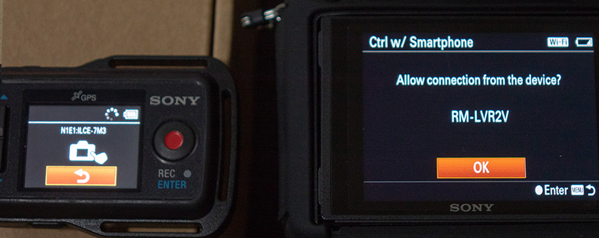
- The RM LVR unit should detect your camera and show this on it’s screen. Highlight the camera and press the shutter release button
- On your camera, the camera should detect that your RM LVR is trying to connect and ask you to approve connection.
- Click “OK” and the camera should enter into remote mode and supply the RM LVR with a live view of your camera.
If the last step fails, start again.
With some cameras, it may ask you to enter a passcode shown on the RM LVR screen. Enter this number on the camera and it should pair automatically moving forward. This has only happened to me once, when trying to pair a RM LVR2 with a A7 Mk3. If that fails then you may not be able to pair.
Mounting
The RM LVR units come with a wrist band and mount and is meant to be worn on the wrist like a watch, which is fine if you’re using it as a remote but if your intention is to use the unit as a vlogging screen, that’s not going to be much use. Fortunately, once the units are removed from the wrist band, they are fairly small and light. Which makes them easy to mount.
The reason I started this site is to apply my interest in 3D printing, into make things for photography and videography. I’ve made a simple mount to mount the RM LVR units to the hot shoe of a camera which will make using these viewers for vlogging, a lot more practical. In addition to being forward acing, the bottom of the mount will also accept a standard 1/4″ screw thread mount which will enable a videographer who is using a cage system to mount it using a double ended tripod screw.

This basic 3d printable mount, in STL format,can be downloaded using this
link.
If you do not have access to a 3d Printer, I can sell you one for USD10 (excluding postage) if you contact me via my contact links or leave me a comment with your email below. The example in the image above was printed in off white to make it stand out, the version I can supply will be printed in black.
This basic mount won’t suit everyone, and I encourage anyone to use the model I have provided to make versions to mount to your specific requirements. It would, for example, be easy to make a version which mounted to a video rig or to a gorillapod. If you do, please let me know and I’ll share this too.
Conclusion
Is it worth getting one of these? Well, I am presenting this as a hack rather than a solution because this hack won’t suit everyone.
If you currently shoot video or vlog with pre A6400 Sony ILCE cameras or have been put off vlogging with older (cheaper) Sony cameras because of a lack of a front facing screen then it’s an easy decision.
For a $100, you get a
front facing screen which runs off it’s
own battery. Because it is also a
remote control, it can be detached, enabling you can place your camera on a tripod or convenient stable spot, walk away from the camera with the remote,
frame using the
zoom and
record. You get dual functionality out of one device. Even used as a stand alone remote, it does most of what the newly released
Sony RMT-P1BT which costs $80 and has a longer range, is properly waterproof and has Live View.
Personally, I find side flipping monitors a bit of a compromise as you would need to angle the camera slightly to the side to be able to view the screen, which introduces distortion. Not a nice thing to have if you’re filming yourself at wide angles of view.
For the serious videographer, there really is no substitute for a dedicated video screen. Not even a flip forward screen will do and for those of you who reckon that you can also touch focus with a flip forward screen, try it. You’ll need two hands to start with and in most situations you’ll end up looking really pinched with two hands fully outstretched. If you’re using any sort of extension, like a gorillapod, that’s a non starter.
Street photographers will like the discreet nature of the remote. It fits neatly within the palm of your hand. You could point your camera at a subject without facing them, glance at your palm to frame and trigger the remote with your thumb.
This is a technique already widely used by street photographers, using apps on their smartphones. The LVRs offer a more discreet option which will not drain your smartphone. Leaving you plenty of juice to post your shots to Instagram, Facebook or just plain old calling people.
On the minus side, $100+ is a lot to pay for a remote control for photographers who only do stills when it will cost you between $10 and $30 for a basic 3rd party Sony remote. The higher priced ones often come with intervolometer functionality. The LVR’s also do not have Bulb mode which potentially rules it out for astrophotographers and landscape photographers. But then again, the lack of screen resolution would probably rule it out for them anyway.
The LVRs also work over WiFi, as opposed to the Bluetooth as used on the RMT-P1 BT, which provides much better range at the expense of battery life. The LVRs have built in batteries which help but the fact remains that your camera has to transmit the live view over WiFi using the camera’s battery.
The WiFi pairing and activation takes 5-10 seconds to initiate and makes it a lot less immediate to use. If you are using the Smart Remote App, it’s also annoying to have to exit the app before you have manual control of your camera.
In the end how useful this will be to you, as with any accessory, will come down to how you shoot. If you already have a Sony action cam and a LVR, or know someone with one, give it a go. It might just surprise you.
Specifications
Power requirements: Rechargeable battery pack: 3.6 V (Internal
battery)
Multi/Micro USB Terminal: 5.0 V
USB charging: DC 5.0 V, 500 mA/800 mA
Charging time: Via a computer: Approx. 4 h and 5 min. Via a AC-UD10 (sold separately): Approx. 2 h and 55 min.
Waterproof performance: Depth of water 3 m (10 feet), 30 minutes continuously (The waterproof performance is not guaranteed under all circumstances)
Operating temperature: -10 °C to +40 °C (14 °F to 104 °F)
Storage temperature: -20 °C to +60 °C (-4 °F to +140 °F)
Dimensions (Approx.): 72.3 mm × 50.2 mm × 20.8 mm (2 7/8 in. × 2 in. × 27/32 in.) (W/H/D, excluding protrusions)
Mass: Approx. 64 g (2.3 oz) (only the main body)
Support page – Manuals, Drivers Firmware
LVR1 – https://www.sony.co.uk/electronics/support/remote-controls-rml-series/rm-lvr1
LVR2 – https://www.sony.co.uk/electronics/support/remote-controls-rml-series/rm-lvr2
by Raymond Yee | March 1, 2019
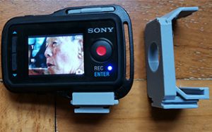 A simple holder for the Sony LVR Remote controls, allowing them to be mounted on camera hot shoes. It also has a 1/4″ screw thread which will allow you to attach it to video cages using a double 1/4″ screw.
Repository: Lost Lens Caps
URL: [ddownload id="3523"]
Author: Ray Yee

by Raymond Yee | October 20, 2018 | Guides, Lens and Camera Modding, Transplant
This article is a wrap up of my documenting my personal experiments with converting compact camera lenses. In my previous articles, I touched on re-mounting lenses on simple 3D printed mounts (Yashica T4) and using complex 3D printed mounts (Olympus Mju II). There has been a 3rd method which I have used and mentioned in my lens modding overview so I’ll end my series of articles on my experiments.
So why stop? Well, in my experiments all I ended up with were a lot of lenses which were sharp in the middle and varying degrees of ‘smeariness’ at the edges. A lot of ‘Lensbaby’ type fun lenses but with not a lot of practical use. OK for portraits and snapshots but not a lot else.
The method of using a surrogate Host lens to rehouse a compact film camera Donor lens is perhaps the most satisfying of the methods I have used so far. By using a host lens, you can usually make use of the host lens’ focusing mechanism, aperture and metal mount. However, there are a specific conditions which the transplant lens which must comply with in order for it to work.
Selection and Preparation
Donor Lens
First and foremost, the donor lens needs to have a decent focusing distance whereby it can focus to infinity at a decent distance away from the focusing plane. Lenses for interchangeable lens cameras are all developed to focus to a set distance between the mount of the camera and the camera’s focusing plane, the surface of the camera sensor on digital cameras. This is known as a flange focal distance and varies from manufacturer to manufacturer. With very few exceptions, lenses on film compact cameras were never meant to be interchangeable and need to focus to a very short distance or the camera would hardly be compact.
The donor lens should also be one which achieves focus by moving the entirety of the lens elements as a single unit and not by moving individual elements. It is easy to determine this as these lenses usually have their aperture behind the last element of the lens. More often than not, the aperture will be a combined aperture and shutter mechanism.
The first hurdle which must be overcome is to find a lens which can focus to infinity whilst remaining at least 3mm above the mount of the camera you intend to mount the lens onto. This is a rough estimate and there are ways to mount the lens recessed into the sensor cavity of your camera, but if you do, the image which will be thrown onto your sensor will be at an angle so acute it would make everything but the center of the image, blurry.
Short flange distance poses the biggest challenge to adapting compact film camera lenses in general, as lenses which have short flange distance throw their image onto the focusing plane at very acute angles, regardless of their optical focal length. On film cameras, this is not an issue as the image falls directly onto the film, which is flat. However, digital camera sensors have various transparent layers such as a Infra Red (sometimes with combined anti-aliasing) and focusing detection cells within it’s surface. These elements sit on a thin pane of optical glass, usually not more than 1mm thick,and it is this glass which causes diffraction and edge smearing.
How to determine if your lens can focus to infinity at a suitable distance from the lens mount? The simplest way would be to ‘lens bash’. Find a relatively dust free indoor location with a view which has a view stretching beyond 1km. Remove the body cap or lens off your camera body and expose the sensor. Keep a dust blower handy. Point the camera body towards the window and turn your camera on. Hold the intended donor lens lens about 2cm away from the lens mount and as centered to your camera sensor as possible. Move the lens slowly back towards the camera sensor whilst looking through the viewfinder or live view of your camera. Use focusing aids like focus peaking if your camera has it. If you can achieve focus on an object over 1km away, at least 3mm before the lens crosses the mount, the lens will have a chance to be successfully transplanted.
The second criteria for transplanting the lens is it’s diameter. If the diameter of the lens is more than 20mm, it cannot be transplanted onto one of the donor lens bodies described below. You can still use the simple mount method or make a complex mount for it using the techniques I have already covered in Project 1 and Project 2.
Host Lens
Selecting an appropriate host lens body is even more restrictive, dependent on the following criteria. The lens needs to have a short flange distance, manual focusing, mechanically simple, and relatively cheap and plentiful in supply.
The first criteria narrows down the field to rangefinder lenses, which usually have a very short flange distance and M42 screw mount lenses* (more on this later)
Being manual focus and mechanically simple are linked. The only autofocus lenses which meet our flange distance requirements above are for modern mirrorless lenses which have complex focusing mechanism which move individual lens elements which immediately disqualify them. Some manual lenses also achieve focus by moving individual elements but regardless of this, the lens will usually focus by moving the main body of the lens away from the camera body when it is at infinity.
At this point, we’ve pretty much narrowed the candidates for host lens to manually focusing rangefinder lenses, the most common of these being those using the Leica M mount and LTM/M39.The last criteria for host lenses is that they have to be cheap and plentiful. Luckily, there are quite a few Soviet era lenses utilizing the LTM/M39 mount which are cheap and in plentiful in supply.

Of these, the Industar 69 (28mm f2.8, M39 mount, half frame) and Industar 50 (50mm f3.5, M39 or M42 mount) come to mind as the Soviets churned them out by the millions. You can pick up individual copies easily for under USD$20 for use as donor lenses, less if you decide to pick up multiple copies as sellers often sell job lots of them. It doesn’t matter if the lens elements on them are damaged, we will be removing them to transplant our compact camera lens on them anyway. Neither does it matter if the focusing is stiff or seized. We will be renovating the lens for our purpose so we can usually fix this provide their is no rust involved.
The only things we need to be mindful of are that these lens barrels are made of aluminum and if this is warped or damaged, we may not be able to focus smoothly. Aside from this, the aperture blades are made of metal which can rust so look out for rusty aperture blades and avoid. If you do end up getting one has rusty aperture blades, you can still make use of the body but remove the aperture.
So which one should you use? The one which I have used the most is the Industar 69 because it has a shorter flange distance than a standard M39 lens, is mechanically simpler and therefore easier to modify and lastly I find that it looks nicer. This lens has a super short flange distance because it was never designed for use on a LTM/M39 camera. It was designed to be a dedicated lens for the, Soviet Chaika half frame camera at a flange distance of 27.5mm, as opposed to the 28.8mm flange distance of a LTM/M39 lens.
I’ve only ever used the Industar 50 for one project which was for a transplanted lens with a 20mm diameter and a long flange distance. This is the only real advantage of the Industar 50, it has a slightly larger lens diameter. For the purpose of describing a lens transplant, I’ll be using the Industar 69, the principle objective steps can be translated to any other donor lens bearing in mind the individual mechanics of the intended host lens.
What you’ll need
- Lens spanner
- Size 0 and 2 Flat head screwdrivers
- Old microfiber cloth or short piled cloth and lots of kitchen towels (not pictured)
- 90+% IPA or methylated spirits
- Blower
- Tweezers
- Lens helicoid grease or white lithium grease (not spray)
- Stiff bristle paint brush. New or thoroughly cleaned (not pictured)
Optional:
Step 1: Disassemble lens to core components
First, remove all the lens elements. Remove the lens retaining ring (image 2) using a lens spanner or a rubber lens tool. The retaining ring is a small threaded screw plate which keeps the front lens elements in place. Removing the retaining ring will free the top most lens element and expose a second set of lens elements which are screwed into place with the same thread which the retaining ring screws into. Remove the second set of lens elements using the lens spanner.
Turn the lens over to it’s back and remove the single set of rear lens elements. Use the lens spanner to release the innermost retaining ring, which is attached to the rear element. Be careful not to loosen the outer rings as the outer most ring holds the aperture mechanism in place.
Next, turn the lens to it’s side. There are 3 sets of screws (left image) which screw onto the lens helicoid and hold the lens barrel in place. Remove these screws with a size 0 flat head screwdriver and keep them somewhere safe.
You will now be able to remove the lens barrel completely. Flip the barrel over. There is a single screw post, screwed into the barrel as indicated with the screwdriver in the middle image. Remove this post using a size 2 flat head screwdriver.
Unscrew the center lens helicoid and you will have disassembled the lens to it’s core component. There is an aperture mechanism within the lens helicoid, which is held in by a retaining ring at the rear of the heliciod. I will not disassemble as doing so will release the aperture blades, which are fiddly to reassemble.
Step 2: Clean and Transplant Lens
For the transplanting of the donor lens, we will work extensively with the lens helicoid itself, therefore the first step would be to clean the heliciod. Use IPA or methylated spirit on kitchen towel first, cleaning off as much of the old helicoid grease. Then, finish off using an old microfiber or short piled cloth. You could just use kitchen towels but I find that it does not really get into the grooves as much as cloth. Short or micro pile cloths are recommended as they do not leave behind fibers.
Next, place the donor lens in the cavity where the front elements used to be. The diameter of this cavity, for the Industar 69 is 18.4mm. If your donor lens is significantly smaller in diameter, then I would suggest that you pad out the diameter with either carefully wound tape or 3d print a sleeve to fit around the donor lens. The latter is preferred as it will create a sleeve of consistent width and ensure the lens is centered to the heliciod.
Once the donor lens is secured to the helicoid, replace the lens element retaining ring. Check to see if it obscures the donor lens significantly. If it does, you may want to grind off a little off the center of the retainer. In my experience to date, it is quite unlikely you will need to do so.
Once the donor lens is secured, check that it does not move around within the heliciod cavity. If it does, add more tape or increase the thickness of the 3d printed sleeve. Then, using a, clean, stiff brush apply a thin layer of grease to the helicoid threads. Applying the grease with a stiff brush and in a thin coat is important as too much grease will only only serve to attract dirt at the bottom of the lens mount as any excess it gets pushed down there.
Once you’ve greased the helicoid, clean and re grease the base of the lens, the same way you cleaned and greased the helicoid. You could have done this when you cleaned the heliciod but I recommended cleaning the helicoid first as there is a lot of handling of the helicoid in transplanting the donor lens which could end with a lot mess if the helicoid grease were not removed first. Once everything has been greased, screw the helicoid into the base of the lens and ensure it rotates smoothly. Then, reattach the lens body immediately so that the greased helicoid is not exposed to dust and dirt.
Step 3: Make Mount and Adjust focusing
There are 6* adapters I use, in combination, for mounting any transplanted lens. I mainly use Sony digital cameras so these adapters are for attaching to Sony E mount cameras but they should be available for other mirrorless camera mounts too (Fuji FX, M4/3 etc.).
- L39 to Sony E mount adapter
- Leica M to Sony E mount Close focusing adapter
- M39 to M42 adapter ring
- M39 to Sony E mount close up adapter (only 1mm or 3mm proud of the camera mount). Also available in a M42 thread instead of M39
- 3D printed mount, various permutations of thicknesses to either M39 mount or Sony E mount
- M39 to Leica M mount adapter ring (not pictured)
With the lens facing away from you, twist the focusing ring (lens barrel) anti clockwise until it will not turn any more. Because we have removed the lens focusing limiting post (step 5 of disassembly), the lens barrel should retract into the body by quite a distance. Keep the lens at this minimum distance whilst trying out the different mounting options. This position represents the position the lens should be at infinity and now all you have to do is try out different mounting options and the mounting solution which will enable you to focus to infinity. I’ve listed out a few permutations below to get you started.
Best solution for a naturally functioning lens with adequate flange distance – Host lens (M39) mounted to a M39 to [Your Camera Mount] adapter
Best solution for a naturally functioning lens with short flange distance – Host lens (M39) mounted to a M39 close up adapter to [Your Camera Mount]
Solution for a naturally functioning lens when the flange distance is between adequate and short – Host lens (M39) mounted to a 3d printed adapter to [Your Camera Mount]
Solution for the shorter flange distance, manual focusing with autofocus option – Remove heliciod from the lens base and lens body, print a 3d mount – Lens helicoid (28mm diameter, 1mm pitch) thread to M39 adapter. Mount helicoid as recessed as possible onto the 3d printed adapter and then on to a M39 to Leica M mount adapter. Mount this combination to a Leica M to Sony E mount close focusing adapter for manual focusing or to a Techart LM EA7 Pro mount for autofocus.
Solution for the shortest possible flange distance, awkward focusing – Remove heliciod from the lens base and lens body, print a 3d mount – Lens helicoid (28mm diameter, 1mm pitch) thread to M39 adapter. Mount helicoid as recessed as possible onto the 3d printed adapter and then on to a M39 close up adapter.
Additional modifications (To be added shortly)
Widening the transplant lens mount area
Using M42 lenses
Removing the aperture completely
Reinstate focus limiting pins
DSC07391
Ricoh MF-1 30mm f3.9
DSC07387
Ricoh MF-1 30mm f3.9
DSC07209
Leica AF C1 40mm f2.8
DSC04204
Nikon AF600 28mm f3.5
DSC03811
Yashica T2 35mm f3.5
DSC00035
Welta Penti Trioplan 30mm f3.5
DSC00032
Nikon AF600 28mm f3.5
Conclusions
Of all the methods I’ve used to transplant compact film camera lenses, this has been the most satisfying. If the lens fit all the criteria for this method of transplant, using a donor lens will give you the most natural handling and usable lens of all the methods I’ve tried. However, this is still far away from being a practical lens. What you would use lenses like this and any of the ones I’ve transplanted by other methods for is up to you. Because they weigh next to nothing, I carry one or two around with me quite often just to get the unique rendering of one of my lenses, usually for portraits and the odd street shot. Weather that sounds like something you would do is down to what you shoot. But I believe there’s a place for them, in the same way Lensbaby have created so many fun lenses which would some people would never consider using both others love.
But what about the lens conversions by people like Miyazaki (MS Optical), who also convert lenses from compact film cameras to M mount? Well, firstly, they do not convert all lenses. The ones they convert are converted to M mount by carefully tuning the lenses using optical machines which colimate the lens and detect chromatic aberrations, equipment not easy to get hold of and require in depth knowledge and experience to operate.
This will be the last of my articles regarding transplanting lenses. I have still a few interesting lenses to convert for digital use, like the Konica WaiWai, but whatever I do will be based on the 3 articles I have already written.
I began my experiments with the intention to create a set of “what if” lenses. Highly portable prime lenses with interesting image rendering/characteristics, to supplement my usual photography load out of lenses. Lenses which I could bring about with me when I would not have brought a similar “proper” lens due to weight or space constraints. And, by and large, I’ve managed to do that with one major caveat. They’re not sharp in the edges, for reasons already mentioned, and is the same reason why most vintage ultra wide angle lenses perform poorly when adapted to digital cameras. So, by all means, have a go if you have a defective compact film camera you’re about to sling into the bin. But, if you do, have realistic expectation of the end results.

by Raymond Yee | August 28, 2018 | 3D Printing, Photography
It’s almost 2 years since my last posting. What had started out as an attempt to combine my main interest in photography and 3D printing and develop content which would interest others with either, but not necessarily both, interests in a potentially interesting mash up.
Unfortunately, personal circumstances got in the way and I’m documenting these events as much for personal memory as much as to lead into where I would like to take my site for anyone who might be interested.
With a dislocated shoulder which needed major surgery and 9 months of rehabilitation, I was unable to do much photography. For a big part of that time, I was unable to even raise a camera up to my eyes, let lone lug around large amounts of photography equipment. Instead, I made frequent trips to the workshop belonging a friend of mine who is a professional camera repairman and learnt what I could about vintage cameras, lenses and photographic equipment in general. Some of this, I will me touching on in future blog entries. Especially on the topic of vintage camera maintenance and what to look out for when buying selected popular vintage cameras.
On the 3D front, things were not much rosier. I started out with a fairly user friendly 3D printer only to see things regress as the domestic 3D printer industry started making more and more printers whose only selling point was that they were cheap. Printer after printer released with touted advanced features that only worked if the user was prepared to do serious amounts of tinkering, essentially 3D companies using paying customers as beta testers and troubleshooter. A far cry from the sub $1000, hassle free, printers I was hoping that would eventually manifest. I started off with a machine which was WI-fi connected, sharable, only required minimum calibration and without having to use a separate software prepare the 3D models for printing. Today, I’m using a atypical consumer focused 3D printer which is non networked, requires constant calibration and requires preparing the models via dedicated software. Most of it can be overcome and all those things I miss can be added but at additional substantial cost and effort. The price of being an early adopter, sure, but my point is that consumer 3D printing is in a rut where the cost barrier is the only one being paid any attention. This has lead to a vicious cycle where the consumers interested in/curious about 3D printing are able to afford printers only to find that it’s a real pain to do even the simplest things and give up on it. This lack of adoption then limits innovation as printer manufactures are unwilling to address other barriers (ease of use, consistency and speed) as they may not get their investment back.
And so we continue…
by Raymond Yee | August 11, 2017
Deprecated: Function create_function() is deprecated in /home/sites/6b/5/511b50458a/public_html/wp-content/plugins/wp-spamshield/wp-spamshield.php on line 2033
 Not wanting to risk bending my Hassy dark slides by dropping them in a pocket, or lose it by setting it down somewhere when shooting, I designed a keeper that hangs ’round my neck and supports the entire surface area of of the Hasselblad V series A12 / A24 dark slide while it’s out of the camera.
I’ve printed in HIPS and Bridge Nylon. I prefer the nylon – it’s a little more flexible than the HIPS, and seems almost “self-lubricating”, so the dark slide inserts easily.
URL: http://www.thingiverse.com/thing:2427190
Author: honhaverstick@thingiverse